

The code is written using behavioral modelling. When the reset is low( '0' ) and the value of Clk changes from 0 to 1, we check the value of J and K through if else statements and set the value of Q and Qbar accordingly.
The reset input in this JK flipflop is said to be asynchronous because its value is checked independent of the state of the clock signal.
The code was synthesized using Xilinx ISE. The RTL schematic of the design is shown below:
VHDL Code for JK Flipflop:
--libraries to be used are specified here
library ieee;
use ieee.std_logic_1164.all;

--entity declaration with port definitions
entity JK_flipflop is
port(Clk : in std_logic;  --positive edge triggered
    J, K: in std_logic;
    reset: in std_logic;  --active high reset
    Q, Qbar: out std_logic
    );
end JK_flipflop;

--architecture of entity
architecture Behavioral of JK_flipflop is

--temporary signals.
--they are used because, output ports cannot be read in the VHDL versions prior to 2008.
signal qtemp, qbartemp : std_logic := '0';

begin

--assign the temporary signals to corresponding output ports.
--'Qbar' is always 'not' of 'Q'.
Q <= qtemp;
Qbar <= qbartemp;

--process for JK flip flop
process(Clk,reset)
begin
if(reset = '1') then           --Reset the output when reset is high
    qtemp <= '0';
    qbartemp <= '1';
elsif(rising_edge(clk)) then
    if(J='0' and K='0') then       --No change in the output
        NULL;
    elsif(J='0' and K='1') then    --Set the output Q.
        qtemp <= '0';
        qbartemp <= '1';
    elsif(J='1' and K='0') then    --Reset the output Q.
        qtemp <= '1';
        qbartemp <= '0';
    else                           --Toggle the output Q.
        qtemp <= not qtemp;
        qbartemp <= not qbartemp;
    end if;
end if;
end process;

end Behavioral;
Testbench code for JK Flipflop:
--library declarations
library ieee;
use ieee.std_logic_1164.all;

--this is how entity for your test bench code has to be declared.
entity testbench is
end testbench;

architecture behavior of testbench is

--Signal declarations
signal Clk,J,K,reset,Q,Qbar : std_logic := '0';
-- Clock period definitions
constant Clk_period : time := 10 ns;

begin

-- Instantiate the Unit Under Test (UUT).
--This style is known as entity instantiation with named association
UUT : entity work.JK_flipflop
    port map(Clk => Clk,
        J => J,
        K => K,
        reset => reset,
        Q => Q,
        Qbar => Qbar);

--Generate Clk with a period of 'Clk_period'
Clk_generation: process
begin
    Clk <= not Clk;  --toggle 'Clk' when half 'Clk_period' is over.
    wait for Clk_period/2;
end process;

-- Stimulus process
stimulus: process
begin
    --change J and K and wait for a Clock period to see the changes
    J<='1'; K<='0'; wait for Clk_period;
    J<='1'; K<='1'; wait for Clk_period;
    J<='0'; K<='1'; wait for Clk_period;
    J<='0'; K<='0'; wait for Clk_period;
    J<='1'; K<='0'; wait for Clk_period;
    --apply reset input and change J and K.
    reset <='1';
    J<='1'; K<='1'; wait for Clk_period;
    J<='0'; K<='1'; wait for Clk_period;
    --reset is made 'low' again.
    reset <='0';
    --now onwards, Q will keep toggling between 1 and 0.
    J<='1'; K<='1'; wait for Clk_period;
    wait;
end process;

end;
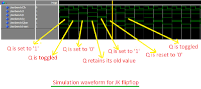
Simulation Waveform:
The codes were simulated in Modelsim. This is a screenshot of the waveform.
In the schematic FDPE represents a single D-type flip-flop with data (D), clock enable (CE), and asynchronous preset (PRE) inputs and data output (Q). Similarly FDCE represents a single D-type flip-flop with data (D), clock enable (CE), and asynchronous clear (CLR) inputs and data output (Q).


0 Comments