

The sine wave's amplitude values can be generated from this online tool - Sine Look up table generator. For this particular version of the code, I used the following settings:
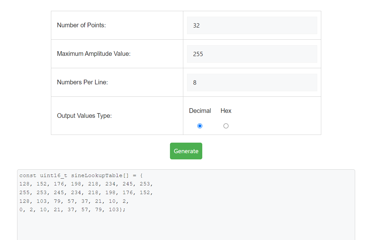
You can generate a sine wave using different settings and paste them in the code given below.
To improve the smoothness and precision of the sine wave use more number of points and a higher value for maximum amplitude value. But remember that if we use too many points, the FPGA resources may not be able to keep up with the size of the ROM needed. So even though its possible theoretically, it may not be practically feasible.
The design can be further improvised by reducing the size of the ROM to 1/4th of its original size. Since sine wave is symmetric, if we have the values for any one quadrant, then the rest of the quadrants can be figured out. This comes at the expense of a slightly more complicated logic in the code.
If you need further explanation you can watch this Youtube video I have created - Generic Sine Wave Generator (LUT Based) in VHDL.
sine_wave.vhd:
--library declarations library ieee;use ieee.std_logic_1164.all;use ieee.numeric_std.all; --try to use this library as much as possible. entity sine_wave is generic(NUM_POINTS : integer := 32; MAX_AMPLITUDE : integer := 255 ); port (clk :in std_logic; dataout : out integer range 0 to MAX_AMPLITUDE ); end sine_wave; architecture Behavioral of sine_wave is signal i : integer range 0 to NUM_POINTS := 0; type memory_type is array (0 to NUM_POINTS-1) of integer range 0 to MAX_AMPLITUDE; --ROM for storing the sine values generated by MATLAB. signal sine : memory_type :=
    (128,152,176,198,218,234,245,253,  --sine wave amplitudes in the 1st quarter.
    255,253,245,234,218,198,176,152,    --sine wave amplitudes in the 2nd quarter.
    128,103,79,57,37,21,10,2,    --sine wave amplitudes in the 3rd quarter.
    0,2,10,21,37,57,79,103);    --sine wave amplitudes in the 4th quarter.

begin

process(clk)
begin
--to check the rising edge of the clock signal
if(rising_edge(clk)) then
--one by one output the sine amplitudes in each clock cycle.dataout <= sine(i);i <= i+ 1; --increment the index.if(i = NUM_POINTS-1) then--reset the index to zero, once we have output all values in ROMi <= 0;end if;
end if;
end process;

end Behavioral;
Testbench - tb_sinewave.vhd:
--library declarations
library ieee;
use ieee.std_logic_1164.all;
use ieee.numeric_std.all;
library std;
use std.env.finish;

--entity for testbenches are always empty
entity tb_sinewave is
end tb_sinewave;

architecture behavior of tb_sinewave is

--declare the component which we are going to test. Here that is "sine_wave"
component sine_wave is
generic(NUM_POINTS : integer := 32;
        MAX_AMPLITUDE : integer := 255
       );
port(clk :in  std_logic;
    dataout : out integer range 0 to MAX_AMPLITUDE
    );
end component;

--generic constants
constant NUM_POINTS : integer := 32;
constant MAX_AMPLITUDE : integer := 255;

--Inputs
signal clk : std_logic := '0';
--Outputs
signal dataout : integer range 0 to MAX_AMPLITUDE;
-- Clock period definitions
constant clk_period : time := 10 ns;
--temporary signals
signal data_out_unsigned : unsigned(31 downto 0);

begin

-- Instantiate the Unit Under Test (UUT)
uut: sine_wave generic map(NUM_POINTS, MAX_AMPLITUDE)
	port map(clk => clk,
            dataout => dataout
            );

data_out_unsigned <= to_unsigned(dataout, 32);

-- Clock process definitions
clk_generate_process :process
begin
    wait for clk_period/2;
    clk <= not clk;
end process;

-- Stimulus process
stim_proc: process
begin
    wait for clk_period*NUM_POINTS*2;
end process;

end;
Note the following about the sine wave generator:
- I have used the library numeric_std instead of std_logic_arith and std_logic_unsigned. Why? Read Why the library "numeric_std" is preferred over "std_logic_arith" and others? for in depth information on this.
- I have used rising_edge(clk) instead of if(clk'event and clk='1'). Why? Read Difference between rising_edge(clk) and (clk'event and clk='1') for more information.
- This same entity can be slightly tweaked to output any wave. Just change the values stored in the sine array.
- The code is fully synthesisable and can be tested on any FPGA, if the relevant connections are made.
- What is the frequency of the generated sine wave?
The frequency depends upon the clock frequency supplied to the sine wave entity and the number of points of sine wave stored in the array.
We can say, freq = frequency_clk / number_of_points; - I cannot see sine wave when I simulate this code. Why?
Its possible to see the shape of sine wave in modelsim software. I got the following waveform from modelsim. Right click on the signal name and choose the correct settings to display the values in analog format.


7 Comments
hi!
ReplyDeleteHow do you do to change the frequency of your sine wave?
Jocelyn
@Jocelyn : The freq of the sine wave is determined by the freq of clk in the above program.Here we need 30 clk cycles for sending one full cycle of sine values.So the period of sine wave is (freq of clk/30).
ReplyDeleteHope I am clear.
heloo jocelyn!
ReplyDeletein the above code i have simulated and runed for 30 sin values but the out put wave does not looks like sin! is their any settings reqired for getting out put wave in the form of sin as the below!
file://localhost/C:/Documents%20and%20Settings/Administrator/Desktop/enp%20final/Synthesisable%20Sine%20Wave%20Generator_files/wave.gif
@prahlad : I never told that the wave will look like a sine wave in the simulator.If you want to test out use a DAC,interface it with FPGA board and connect the output of DAC to an oscilloscope.
ReplyDeleteOr another thing you can do is take a graph sheet draw the output values Vs time.You will get a sine signal.If you still not getting contact me.
really, people probably should be using the coregen dds compiler. but overall, this shows the basic concept.
ReplyDeleteA DDS will generally exploit the symmetry in the sine wave -- only 1/4th of the sine wave values are needed.
this allows a larger table to be used. using a lot of entries allows the user to increment by N, to generate other frequencies.
@Chris : I do agree. But if you just use core gen IP's for each and everything then how will you learn.This is a basic code where you can see how it works.I have mentioned in this post itself that,"The code can be modified for efficient use of memory so that,only the first (pi/2) values are stored in the ROM".
ReplyDeleteI just left it as an exercise for readers.
Thanks,
ReplyDeleteI need to learn how to use the DAC so I can play with this!!